Write a Circuit Diagram
Have you ever tried to install and use LTspice, but failed in the middle of typing while looking at a reference book or failed to get the desired result due to an error?
To solve such problems here I will introduce「How to Write a circuit diagram in 5 Steps」.
5 Steps to Write a circuit diagram
This time, let’s make a circuit diagram using the switching regulator LT8614.
Step 1
Launch LTspice by clicking the LTspiceXVII icon on your desktop or by selecting LTspiceXVII from the Start menu.
 Figure 1:Launch LTspiceXVII
Step 2
Click New Schemas in the upper left corner of the menu or select New Schemas from the File menu to open a blank sheet (Draft 1. asc file) for schematic creation.
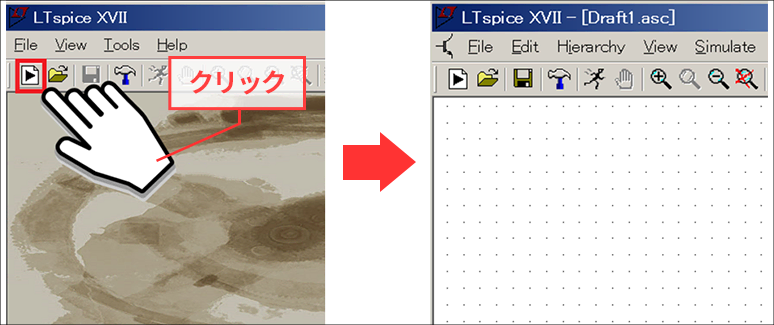 Figure 2:New Schematics
Step 3
Click a component (red box) on the menu or press F2. This will launch a menu that will select a part called Select Component Symbol.
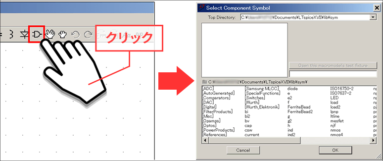 Figure 3:Select Component Symbol
Step 4
Enter the part name "LT8614" that you want to simulate in the red frame of "Select Component Symbol" menu (Figure 4). The part will be selected automatically.
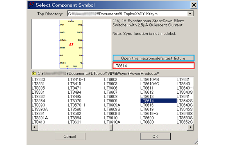 Figure 4:Select component
Step 5
Finally, click the Open this macromodel's test fixture button in the blue box in Figure 4.
You can then obtain a schematic with the peripheral parts placed.
- Some products do not have schematics, in which case the "Open this macromodel's test fixture" button will not be activated.
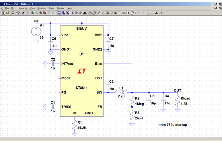 Figure 5:LT8614 schematics
Run the simulation
By clicking "RUN" to run the simulation you can check the operation of the circuit.
This circuit is called "JIG".
This JIG file is a circuit with 5V output setting. If you need a circuit diagram with the required input / output conditions (for example, 3.3V output), check the product data sheet first.
You can then modify and run the JIG file according to the circuit diagram on the datasheet to obtain the desired simulation results.
By using the JIG file, you can improve the efficiency of circuit diagram preparation and reduce input errors.
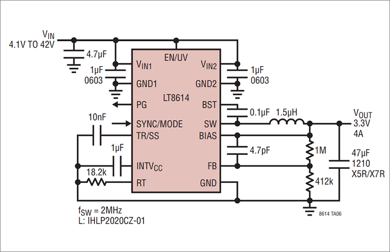 Figure 6:From the datasheet(circuit with 3.3V output setting )
